文章目录
Recently, while working on a DIY project, I needed to measure voltage, current, and power in the circuit. After comparing several chips, I decided to use the INA219 chip from Texas Instruments. Coincidentally, I had previously used an INA219 module to build a simple power meter, which made me quite familiar with it.
The official introduction of INA219 is as follows:
The INA219 is a current shunt and power monitor with an I2C- or SMBUS-compatible interface. The device monitors both shunt voltage drop and bus supply voltage, with programmable conversion times and filtering. A programmable calibration value, combined with an internal multiplier, enables direct readouts of current in amperes. An additional multiplying register calculates power in watts. The I2C- or SMBUS-compatible interface features 16 programmable addresses.
The usage of INA219 is relatively simple. Data can be read directly through the I2C bus, and it supports a maximum measurement voltage of 26V with 12-bit precision, which satisfies the requirements in most scenarios. On the OSHWHub, many USB power meters also use this chip.
Schematic Diagram
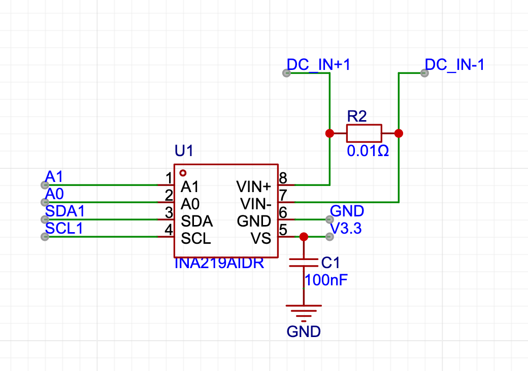
INA219 requires only a few external components to operate. Adding a bypass capacitor to the power supply and a current sensing resistor completes the setup.
A0 and A1 are used to specify the address of INA219 when communicating via I2C. If there is only one INA219 chip in the circuit, these two pins can be directly connected to ground.
Typically, INA219 is used for high-end sensing. Therefore, in the circuit, VIN+ is connected to the positive terminal of the measured power source, and VIN- is connected to the input terminal of the circuit using the power source.
By default, INA219 uses a 0.1-ohm current sensing resistor. However, in practical applications, the current sensing resistor can be replaced with a different value based on the current range to be measured.
Using INA219 with Arduino
In Arduino, there are several libraries available to support the setup and data reading of INA219. After comparing several libraries, I ultimately chose the INA219_WE library. It can be easily installed through PlatformIO or cloned from GitHub to be used in the source code.
// The address for communication with INA219 when both A0 and A1 are grounded is 0x40.
INA219_WE ina219 = INA219_WE(0x40);

void readINA219() {
    // Voltage drop across the current sensing resistor
    float shuntVoltage_mV = ina219.getShuntVoltage_mV();
    // Power supply input voltage
    float busVoltage_V = ina219.getBusVoltage_V();
    // Magnitude of the sampled current
    float current_mA = ina219.getCurrent_mA();
    // Magnitude of power in the circuit
    float power_mW = ina219.getBusPower();
}
Setting the gain
By default, INA219 uses the PG_320 gain setting, which allows a maximum voltage drop of 320mV across the current sensing resistor. When using a 0.1-ohm current sensing resistor, this corresponds to a maximum current measurement of 3.2A with a minimum resolution of 780uA.
If higher accuracy is required, the gain of INA219 can be adjusted based on the specific measurement circuit. For example, if the measured current does not exceed 800mA, the PG_80 gain setting can be used to achieve a minimum resolution of around 20uA.
The gain can be set using the setPGain method:
ina219.setPGain(PG_80);Using software emulation for I2C
In general, when using the MCU's built-in I2C bus, there are usually no compatibility issues when communicating with the INA219. However, if the MCU's I2C bus is insufficient, it may be necessary to use software emulation for I2C.
When using software emulation for I2C, I searched for some libraries on the PlatformIO platform. However, during the process of using it with ESP32, there were communication errors. After testing, it was found that using AceWire for software emulation of I2C allows normal communication with the INA219.
If there is a need to communicate with the INA219 using software emulation for I2C, you can try using AceWire.
Sampling resistor heating
If the sampling resistor is relatively large and the measured current is high, there may be a significant heating issue with the sampling resistor. In a previous test, when using a 2512 0.05-ohm sampling resistor with a continuous current of around 3A, the temperature of the sampling resistor would rise to 66 degrees Celsius.
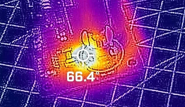
Without proper heat dissipation, this temperature is not acceptable. Therefore, if there is a need for continuous high-current sampling, it is recommended to compromise on some sampling accuracy and use a smaller sampling resistor. This way, it can effectively prevent the sampling resistor from heating up too much.
Expanding the current range
By default, when using the INA219 with a 0.1-ohm sampling resistor, the maximum measurable current is 3.2A. However, in the case of USB PD charging with a maximum of 100W, this exceeds the measurement range.
In such situations, a smaller sampling resistor can be used. Although the sampling accuracy will decrease, an accuracy of around 1mA is sufficient for most scenarios.
Conclusion
The INA219, as a popular power monitoring chip, is quite user-friendly in DIY projects. It comes in an SOP-8 package, making it easy for manual soldering. When used with Arduino, it has a strong open-source library support, allowing for plug-and-play functionality right out of the box.

0 条评论。